4G/5G Traffic Monitoring using UPN
In 4G/5G traffic monitoring using User Processing Node (UPN), the UPN processes the subscriber information that is extracted from the PFCP packets and correlates with the GTP-u traffic without the CPN. When the traffic contains the user's field information such as IMSI, IMEI, you can use the 4G/5G traffic monitoring using UPN.
The PFCP allows optional Informational Elements (IE) that contain SUPI/IMSI, PEI/IMEI, and GPSI/MSISDN information of the subscriber during PFCP session establishment request.
Note: The amount of time to restore from backup can take up to 11 minutes.
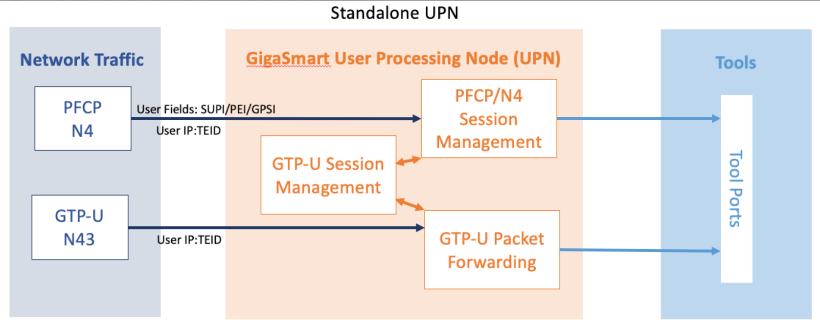
The UPN performs the following activities in the Standalone mode:
-
Processes the PFCP session establishment request and extracts the SUPI/IMSI, PEI/IMEI, GPSI/MSISDN User IP, and TEID for both endpoints. The information in the PFCP traffic is used to populate the UPN's session table.
-
Correlates GTP-U traffic based on the subscriber information from PFCP. The GTP-U look-up is correlated based on the IP and TEID.
PFCP (Packet Forwarding Control Protocol) is a 3GPP Protocol that is communicated on the Sx/N4 interface between the Control Plane (CP) elements and User Plane (UP) elements. The CP element programs the UP element with policies on how to forward packets. PFCP packets convey information in the form of Information Elements (IE). PFCP allows an optional IE called User Fields that contains IMSI/SUPI, IMEI/PEI, MSISDN/GPSI information of the Subscriber during PFCP Session Establishment Request.
The PFCP (Packet Forwarding Control Protocol) is a 3GPP Protocol that is communicated on Sxa, Sxb, N4 interface between the Control Plane (CP) elements and User Plane (UP) elements.
The CP element programs the UP element with policies on how to forward packets. The CP function controls packet processing in the UP function by establishing, modifying, and deleting the PFCP session.
The following diagrams explain the functioning of UPN in Stand-alone mode:
- A Stand-alone UPN traffic monitoring session can be created only when there is atleast SUPI in the user fields.
- You cannot perform RAN correlation or Network Slicing Correlation in Stand alone UPN traffic monitoring
- UPN does not receive SFFP messages in the User field parse mode.
The following are the points to remember while configuring 4G/5G traffic monitoring using UPN:
- You must enable the stand-alone mode in UPN while creating the solution in Ansible.
- Once the stand-alone mode is enabled, UPN cannot connect with the CPN, and you cannot change the mode. To change the mode, you need to delete the UPN from the solution and
- add a new one.
PFCP Messages
Session Related Messages
These messages are exchanged between Control Plane and User Plane function at the subscriber level. These messages are load balanced based on the IMSI of the subscriber.
| Session establishment request/response |
| Session modification request/response |
| Session deletion request/response |
| Session report request/response |
Node Related Messages
The PFCP node related message packets are broadcast to all the ports which are part of the port-group in FS/WL maps. These messages are not specific to any subscriber. The load balancing based on IMSI is not possible for these packets. They continue to broadcast as per the existing behavior.
| Heartbeat request/response |
| PFCP PFD management request/response |
| PFCP association setup request/response |
| PFCP association update request/response |
| PFCP association release request/response |
| Version Not supported response |
| PFCP Node report request/response |
| PFCP session set deletion request/response |
PFCP Load Balancing
The PFCP packets received are load balanced based on the IMSI present in the "IE Type: UserID".
Once the PFCP packet is received, the mobility application will parse the packet and create or update or delete the corresponding sessions or tunnels in the session table. The IMSI present in "IE Type: UserId" is stored in the session table and used for load balancing. Once sessions or tunnels are created, map lookup is performed for the PFCP packets. If there is a match in the IMSI, the packet is sent to only one port from the configured Load Balancing application based on the IMSI hashing. The hash value string from IMSI string present in the "IE Type: UserId" is added to the packet before sending to the Load Balancing application. The Load Balancing application will do Load Balancing logic based on this hash string and choose any one port to send the packet out.
Licensing Requirement:There is no need of a separate license for PFCP Load balancing. The existing license for Standalone UPN is sufficient for this feature.
Single Engine: The PFCP packet is sent to only one GigaSMARTS engine. Based on the map lookup, the packet will be forwarded to the Load Balancing application and sent to only one port based on the IMSI hashing.
Grouped Engine: ThePFCP packet is sent to all the GigaSMART engines configured as part of the engine group configuration. The PFCP packets are processed as per the existing design, but the packets are sent out only through one port in the LoadBalancing application in the leader engine.
Map Configuration
The 4G and 5G traffic passes through a single map in standalone mode. The user can configure a 4G map through which both 4G and 5G traffic passes. You do not need to configure separate maps for 4G and 5G traffic.
Note: The single map configuration is applicable only for standalone UPN. For legacy GTP and 5G user need to configure 4G and 5G maps separately
Required License for UPN Standalone Single Map type: 5G.
-
For 5G and GTP flow sample with rule percentage (0 or 100), the 5GC and GTP_MAX licenses are required.
-
For 5G and GTP flow sample with rule percentage in all ranges (between 0 to 100) or for GTP Whitelist, the 5GC, GTP_MAX, and FVUE licenses are required.
Stateful Session Recovery
It is crucial to back up the information from the correlated session table to avoid discrepancies during engine reboots and connection failures. After a successful reboot, the information saved as part of the persistence file is populated back into the mobility database.
Mobility applications require stateful session recovery to persist their data between node reboots and connection failures. This feature aims to extend the support available in LTE/5G mobility applications to Standalone UPN functionality. The session table is backed up every 10 minutes. You cannot change the backup time interval.
File Age Timeout— Specifies the time the backup file is valid, in minutes. After this time expires, the backup file is stale. The default is 30 minutes.
<10 ~ 1440> - 10 minutes is the minimum and 1440 minutes is the maximum value for file-age-timeout.
Restart Age Timeout—Specifies the time interval following a reboot for aging-out sessions, in minutes. This is a shorter interval than that specified using the gtp-flow timeout. The gtp-flow timeout disconnects a GTP session if it has been inactive for the timeout value, which has a default of 8 hours. The restart-age-timeout default is 30 minutes.
<10 ~ 1440> - 10 minutes is the minimum and 1440 minutes is the maximum value for restart-age-timeout
GTP Persistence Interval—Specifies the time interval between backups, in minutes. The default is 10 minutes.
<10 ~ 1440> - 10 minutes is the minimum and 1440 minutes is the maximum value for restart-age-timeout.
5G Stateful Session Recovery
Required License: 5G Correlation
5G stateful session recovery provides session persistence for GigaSMART 5G applications, including 5G flow filtering, 5G forward listing, and 5G flow sampling. In this method of recovery, 5G sessions are backed up periodically so that they can be recovered faster after a GigaSMART line card reboot or a node reboot.
5G stateful session recovery requires additional memory for storing backups. GigaVUE-HC3 has the required memory.
Using 5G stateful session recovery, the 5G session tables in the GigaSMART line card memory are periodically backed up to the control card memory on the node and stored.
You should configure an interval for how often the backups occur, such as every 10 minutes. If 5G stateful session recovery is enabled and the GigaSMART line card is rebooted, the 5G session tables are restored automatically following the reboot.
The last stored backup file is downloaded from the control card to the GigaSMART line card using FTP. The session table is repopulated from the last stored backup file to each GigaSMART engine, up to 8 engines. Packet count statistics for sessions are saved and restored.
Depending on the size of the session table, the amount of time to restore from the backup might take as much as 3 minutes. During that interval, traffic is blocked to the virtual port on the GigaSMART line card. Once the session table is read and populated, traffic is allowed.
Depending on the interval between backups, there could be differences between the stored state and the current state of the system, for example, map configuration could change, or sessions could be added, modified, or deleted.
Load balancing information is not persisted, so after a session table is repopulated, a session that was once sent to one load-balanced port may be sent to a different load-balanced port after the reboot. However, for SUPI-based load balancing, the traffic is sent to the same port as it was before the reboot.
5G stateful session recovery works in a cluster environment; however, the cluster leader must remain the same.
Configure 5G Stateful Session Recovery
To enable 5G stateful session recovery, as well as to configure timers, do the following:
1. On the left navigation pane, click , and then select Physical>Nodes.
2. From the device view, select GigaSMART > GigaSMART groups.
3. Click on the alias of the GigaSMART group.
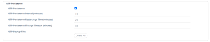
4. Select GTP Persistence in the GTP Persistence fields under GigaSMART Parameters. The timers are pre-configured with default values.
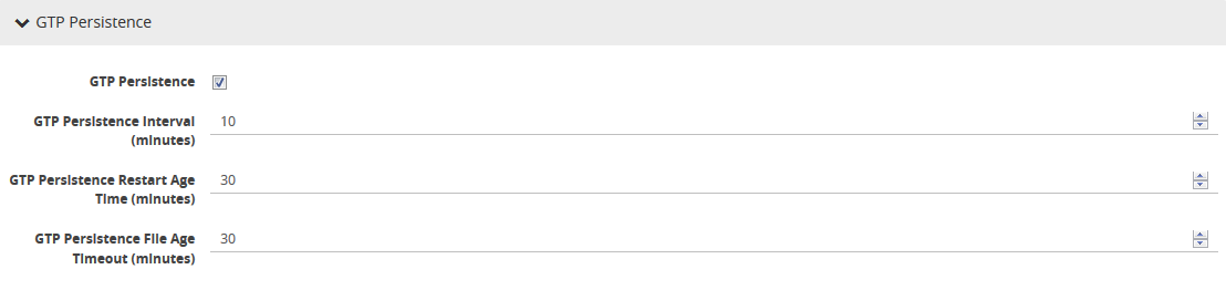
| 1 | GTP Persistence GigaSMART Parameters |
Use the System widget on the Overview page to determine the amount of memory. The size of memory is 24Gb in an upgraded system.
View Backup and Restore Information
To view the System information, select Overview from the Navigation pane. The amount of free and used memory is displayed in the Memory field.
To view backup and restore information for GTP Persistence:
1. Select GigaSMART > GigaSMART Groups > GigaSMART Group.
2. Click on the alias of the GigaSMART group.
A Quick View appears for the selected GigaSMART group.
3. Scroll down to GTP Persistence. In Figure 26-63, GigaSMART Group gsgrp-1_4_e1 is selected and the Quick View is displayed.
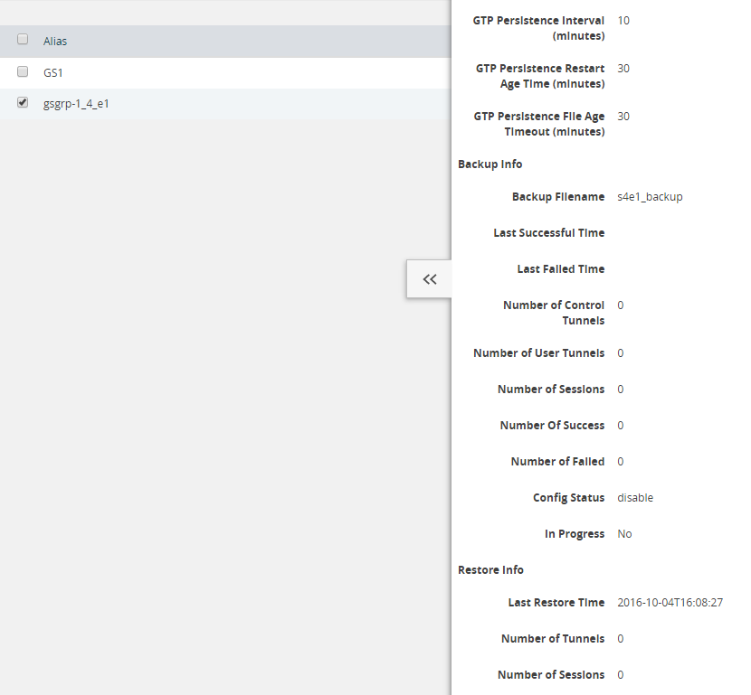
Figure 2 GTP Persistence Information
Configure GTP Overlap Mapping
The configuration of GTP forward listing and GTP flow sampling maps that are part of the GTP overlap flow sampling map group follow the same configuration considerations discussed previously in GigaSMART GTP forward listing and GTP Flow Sampling. As is the case with regular non-overlap GTP mapping, GTP forward listing selects specific subscribers based on IMSI, whereas GTP flow sampling uses map rules to select subscribers and then forward a percentage of the packets to tool ports.
Configuration Considerations
This section details certain configuration considerations that apply only to the configuration of GTP forward listing and flow sampling maps for GTP overlap flow sampling maps.
About Standalone UPN Flow Sampling Map Mode and Port Groups
A second level type map specifying Standalone UPN flow sampling map mode must be selected to configure Standalone UPN forward listing and flow sampling maps.
To configure a Standalone UPN whilelisting map in overlap flow sampling map mode, select Type as
Second Level and Subtype as Flow Whitlelist Overlap in a map.
To configure a GTP flow sampling map in GTP overlap flow sampling map mode, select Type
as Second Level and Subtype as Flow Sample Overlap in a map .
You can configure one GTP forward listing map and one GTP flow sampling map pair that contain traffic policies corresponding to one destination port group. The load balanced port groups can contain a single port, a port range, or a GigaStream. Note that, starting in software version 4.8, port groups used in GTP overlapping maps support GigaStream.
The maximum number of port groups per single GTP overlap flow sampling map group is six.
For more information about port groups, refer to Port Groups.
Maximum Number of Port Group Members
Use the following sequence to help you determine the maximum number of port group members:
1. Determine the number of members per port group and add 1 to the number.
2. Multiply each port group result times each other.
3. The total multiplication should not exceed 1024.
For instance, assume the following configuration in a GTP overlap mapping group:
■ Port Group 1—2 load balanced Gigastreams
■ Port Group 2—3 load balanced Gigastreams
■ Port Group 3—1 load balanced tool port
■ Port Group 4—1 load balanced Gigastream
■ Port Group 5—4 load balanced tool ports The total number becomes:
(2+1)*(3+1)*(1+1)*(1+1)*(4+1) = 240
Since this does not exceed the maximum number of multicast IDs (1024), the tool configuration shown is accepted.
Standalone UPN Flow Sampling Map Priority
Since a packet matches multiple maps independently the concept of second level map priority does not apply to Standalone UPN flow sampling maps. A standalone UPN flow sampling map pair consists of one Standalone UPN forward listing map and one Standalone UPN flow sampling map having the same destination port group. Within a Standalone UPN flow sampling map pair the forward listing map rules will be applied before the flow sampling map rules.
Virtual Port Configuration in Standalone UPN Mode
In Standalone UPN map configuration, the virtual port sending traffic to all the port groups need to be configured in Standalone UPN mode.
To configure the virtual port with Standalone UPN mode, select Standalone UPN when configuring the virtual port.
Overlap Support
Currently, a GTP packet can be destined to at most one destination tool. You can now receive multiple copies of a GTP packet that are sent to various tools (One copy per tool set).


